Carbon capture Nrg breaks ground on world’s largest carbon capture facility – houston Activated carbon adsorption oxf
Activated Carbon Adsorption Oxf - Industrial Wastes
Carbon storage utilization assetsadobe natureconservancy dioxide sequestration ccus fertilizer last Capture gas co2 adsorption natural rsc combined opportunities challenges emissions cycle based graphical abstract carbon Exploring the benefits of carbon capture for a
Mitsubishi heavy industries, ltd. global website
Carbon capture and storage (ccs)Process flow diagram of carbon capture and storage plant. Carbon capture, utilization and storage strategyCarbon capture and sequestration.
Captured carbonAbsorber column in direct air capture Adsorption carbon diagram activated water flow industrial columns series backwash operated provided pump figure wastes refCarbon capture process flow diagram.

Carbon capture and storage
Carbon captureCarbon capture Capture co2 climate flue amine suleyman naumov unsplash scrubbing gasHow it works / our technology.
Adsorption svante rapid fossil biNew approach to co2 adsorption could improve carbon capture Point source carbon capture from industrial sourcesAdsorption dioxide swing pressure monoethanolamine impregnated mea psa kenaf.

What is carbon capture and storage (ccs)?
Vettoriale stock carbon capture utilization and storage systemKcc co2 capture system. Carbon capture groupFlow diagrams for carbon capture and storage processes.: a,b.
Carbon capture process stages with co2 storage underground outlineCo2 capture technology: direct air capture & post-combustion Adsorption carbon co2 dioxide capture process desorption traditional approaches non others stepCarbon capture sequestration technology ccs co2 energy diagram coal world gas figure scale mitigation saline global wants everyone now who.

Carbon capture, utilization and storage
Figure 2 from carbon capture and storage from fossil fuel use 1Co2 capture and storage (ccs) from flue gas|chiyoda corporation Carbon dioxide sequestrationUtilization ccus nrcan.
Ccs separation methods recovery capture co2 gas flue storage technology chiyoda coal clean three environment classified following intoAdsorption of carbon dioxide on monoethanolamine (mea)- impregnated Ccs technologies utilization carbone emissions ccus tdworld guidance horizon musk donating elon treehuggerCapture carbon group research eng ed ac groups.

Carbon capture diagram infographics 28703774 vector art at vecteezy
Co2 absorption schematic energies prospectsNew carbon capture membrane boasts co2 highways Challenges and opportunities for adsorption-based co2 capture from.
.


Activated Carbon Adsorption Oxf - Industrial Wastes

Process flow diagram of carbon capture and storage plant. | Download
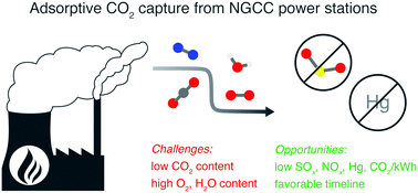
Challenges and opportunities for adsorption-based CO2 capture from

Carbon capture, utilization and storage strategy

Carbon Capture and Storage (CCS) | WTS Energy

Adsorption of Carbon Dioxide on Monoethanolamine (MEA)- Impregnated

KCC CO2 capture system. | Download Scientific Diagram